Just noting the response in the FB group here for reference - we have seen intermittent issues with throttle position sensors that are as easy to remedy as simply unclipped the harness from the pedal, plugging it back in, then restarting the car.
I didn't realize this got posted. I fixed the 303 car and was going to do a thread about it.
On most fly by wire throttles, once a code is set, you have to reset the code before the system will try again, EVEN AFTER THE ISSUE IS PHYSICALLY FIXED. I presume this is the same for the Suzuki per norms.
So, I am not sure that cycling the master switch resets the codes on this. I may induce a TPS code again and find out and report back.
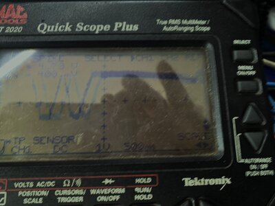
But in this case, my scan tool communicates with the suzuki. It had several codes for the TPS and specifically called out "tps circut d" and "tps circuit E".
So I actually initially reset the codes and the throttle worked again for a little bit, but then it failed again shortly, and the codes were back. A new tps sensor failure is very suspect, (I actually originally thought it was more likely the dogbone that actuates it came off). But that was ok, so I went hunting for a bad circuit.
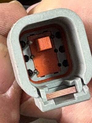
There is a 6 cavity Duestch connector on the TPS sensor pigtail that has been used for the RUSH car wiring harness. The root of the problem is that the locks for the male pins did not get engaged properly when building the plug. So, plugging it in once, stuff works because the pin might be touching the other half of the connector but then shortly there is an open circuit creating the behavior that was reported, which is due to a open circuit from the pin being pushed back.

So the middle pin on that side, and also one you cant see in the pic on the near side, were pushed back in.
If you are having TPS problems, this is worth a look.
Altho this is an easy mistake to make (I have done it myself building race car harnesses) that is no consolation if you have to DNF with the car just idling!!

Once you get them clipped, that orange block keeps the lock engaged to hold the pin firmly. Note in this application only 4 pins are used of the 6 available cavities. I forgot to get pic of final assy fix.
Also for future reference, for anyone coming across this chasing a problem, the wire colors do the following.
Brown - Sytem 5 volt reference, should be solid. (5.3 on mine)
Blue - System Ground.
Black - Voltage signal that follows the pedal sweep. I presume this is a secondary signal. Mine went from .2-3.6 on pedal going from off to full throttle.
White - Voltage signal that follows the pedal sweep. I presume tis is the primary signal. Mine went from .53 - 4.86v on pedal going for off to full throttle.
Many FBW systems have multiple signal to confirm logic. Again, I don't know the suzuki design specifically, but I would expect norms.
Anyway, yes its all good now. Took an afternoon to run down tho.
Hope this helps in the future.
Kyle